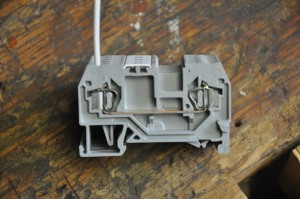
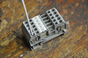
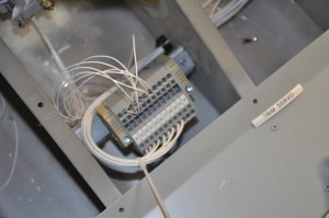
 My professional working life largely revolves around designing instrumentation and control systems for industrial applications. Wiring of devices in these applications is always accomplished thru the use of terminal blocks. Typically these terminal blocks serve as places to conveniently land conductors as they travel from device to device to power or ground. I carried this design philosophy forward into the RV9A electrical system by using lightweight WAGO spring loaded terminal blocks mounted on DIN rails. The spring loaded terminal blocks are face terminated as opposed to side terminated. This feature makes it real easy to stick the stripped conductor into the terminal block while holding the spring keeper open with a small bladed screwdriver.
 As you are looking directly into the terminal block opening, its easy to see when you have the conductor inserted correctly. Release the spring keeper and you have a solid connection which is extremely vibration resistant. This is the real benefit of the spring loaded terminal block as opposed to screw type terminal blocks. The screws will eventually loosen over time with temperature change and vibration.
All wiring used in the RV9A is MIL spec wire with high temperature TEFZEL insulation. Some builders choose to use many different sizes of conductors in their projects based mainly upon the anticipated load it will feed and calculated voltage drop which can occur on long runs in the aircraft. I chose to simplify the design and use #16 awg wire to supply the majority of the loads in the aircraft.  The only exception to this is the circuit wiring associated with the boost pump which is #14 awg and the #12 awg which is used to connect the satellite ground buses back to the main firewall ground point. As described elsewhere in this section, all wires are identified with marked heat shrink sleeves. This is a standard practice in industry and makes sense to carry over into the RV9A wiring system. I use a “destination” wiring scheme and wire number on each wire tag. When you look at the conductor the tags gives a short text description of where it is going and a wire number which is listed on my schematic for that system (or sub-system). As I build and wire, I “As-build” my schematics tyo make sure they accurately reflect what was actually done. Five years from now, I will have totally forgotten what I did so good reference documents are essential.
All grounding in the aircraft returns to a system of distributed ground busses. Even though the aircraft is metal in construction, no circuits will rely on the aircraft frame for the return path of the circuit to the battery ground post. Three ground busses are located behind the instrument panel. Two of these are for general electrical circuits and one is specifically for avionics. The ground busses are electrically connected back to the main firewall ground lug which passes thru the firewall in an insulated bushing. The battery negative terminal and engine ground strap connect to this ground post on the engine side of the firewall. Why so concerned about grounding when the frame would accomplish the same task? Ground loops, simply described as tiny difference in the resistance between the devices you are connecting to the frame at one point in the aircraft and the final negative terminal post on the battery. These resistance differences will force the electrons to take a different path back home to the battery than expected, sometimes causing mysterious problems when high electrical noise loads find their way into radio or avionic circuits. It’s always easier to plan and build for the worse case than try and find and fix when the wiring is all done and tied up.