In my first real job out of college, I worked in the Manitoba Hydro (large electrical utility) electrical panel shop, learning how the large electrical panels used in generating station control rooms and transmission stations are built. All wiring in these panels is done with switchboard class wire with similar temperature resistance specifications as we use in our aircraft systems. All wiring was neatly gathered and then tied together using a waxed cord that laid flat and held tight. 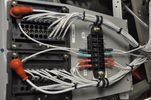 To remove it, side cutters were the best tool. As the plastic industry evolved, the wire wraps or Tie-Wraps came on the market. They have mostly replaced the waxed cord as fast and convenient method of gathering wires into bundles. I don’t like tie wraps. They are OK for temporary wiring gathers as you add more and more conductors to your bundle but once done they must be replaced with an approved wire tying cord. Why? Nylon tyraps are not temperature matched for the wire in your aircraft. They will slash your arm when you reach up into that black hole behind the panel. Most builders do not properly twist the excessive wrap lead off when done.
 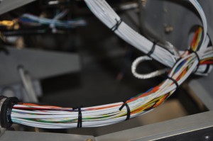 They cut them off with side cutters, usually at an angle, rarely flush with the locking pin of tywap. This leaves a collection of razor sharp nylon stubs waiting for your bare skin to pas over. I advise spending the 20 bucks for a roll of wire tying cord and learn the tying trick. The results are professional looking and not hazardous to the touch.
Category Archives: Electrical System
Wiring and Terminal Blocks
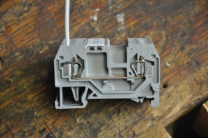 My professional working life largely revolves around designing instrumentation and control systems for industrial applications. Wiring of devices in these applications is always accomplished thru the use of terminal blocks. Typically these terminal blocks serve as places to conveniently land conductors as they travel from device to device to power or ground. I carried this design philosophy forward into the RV9A electrical system by using lightweight WAGO spring loaded terminal blocks mounted on DIN rails. The spring loaded terminal blocks are face terminated as opposed to side terminated. This feature makes it real easy to stick the stripped conductor into the terminal block while holding the spring keeper open with a small bladed screwdriver.
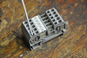 As you are looking directly into the terminal block opening, its easy to see when you have the conductor inserted correctly. Release the spring keeper and you have a solid connection which is extremely vibration resistant. This is the real benefit of the spring loaded terminal block as opposed to screw type terminal blocks. The screws will eventually loosen over time with temperature change and vibration.
All wiring used in the RV9A is MIL spec wire with high temperature TEFZEL insulation. Some builders choose to use many different sizes of conductors in their projects based mainly upon the anticipated load it will feed and calculated voltage drop which can occur on long runs in the aircraft. I chose to simplify the design and use #16 awg wire to supply the majority of the loads in the aircraft. 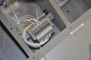 The only exception to this is the circuit wiring associated with the boost pump which is #14 awg and the #12 awg which is used to connect the satellite ground buses back to the main firewall ground point. As described elsewhere in this section, all wires are identified with marked heat shrink sleeves. This is a standard practice in industry and makes sense to carry over into the RV9A wiring system. I use a “destination” wiring scheme and wire number on each wire tag. When you look at the conductor the tags gives a short text description of where it is going and a wire number which is listed on my schematic for that system (or sub-system). As I build and wire, I “As-build” my schematics tyo make sure they accurately reflect what was actually done. Five years from now, I will have totally forgotten what I did so good reference documents are essential.
All grounding in the aircraft returns to a system of distributed ground busses. Even though the aircraft is metal in construction, no circuits will rely on the aircraft frame for the return path of the circuit to the battery ground post. Three ground busses are located behind the instrument panel. Two of these are for general electrical circuits and one is specifically for avionics. The ground busses are electrically connected back to the main firewall ground lug which passes thru the firewall in an insulated bushing. The battery negative terminal and engine ground strap connect to this ground post on the engine side of the firewall. Why so concerned about grounding when the frame would accomplish the same task? Ground loops, simply described as tiny difference in the resistance between the devices you are connecting to the frame at one point in the aircraft and the final negative terminal post on the battery. These resistance differences will force the electrons to take a different path back home to the battery than expected, sometimes causing mysterious problems when high electrical noise loads find their way into radio or avionic circuits. It’s always easier to plan and build for the worse case than try and find and fix when the wiring is all done and tied up.
Fuses
I decided long before laying out the instrument panel that I would keep it clean and simple. This influenced my decision to use fuses exclusively for protecting all circuits in the aircraft. Having flown my 701 for over 10 years, I never had the need to reset a tripped breaker button. If one did pop out, would I attempt to reset it in flight unaware of what caused it to pop in the first place? The RV9A electrical system is protected entirely with automotive style blade fuses. The fuses are contained in two Bussman Fuse and Relay Modules. These two modules provide up to 20 fuses and 10 SPST relays. The modules have rear entry wiring which provides a nice clean appearance. Both these modules, which I refer to as PDM (Power Distribution Modules) are located on a hinged panel that tucks up on the passenger side of the firewall. A single dutz style fastener holds it up. Undo the fastener and the hinged panel drops into view above the passengers rudder pedals. As the fuses are feed from a bus on each module, I also needed to add a fuse block which contained 6 individual fuses. Two of these fuses are required for the Eagle Power Management Module. It supplies power to the Left and Right engine control computers.
It was interesting to see the Vans Factory RV12 equipped with similar blade style fuses when I was at Arlington EAA convention in 2010. It was the first time I was aware that they had taken this route. Guess I am not too far off the beaten path with this approach (other than I moved the fuses out of sight for a cleaner appearance
Primary Power System
When I originally designed the RV9A electrical system, I used the Vertical Power VP100 Subaru schematic as a reference. This was mainly based upon my original intent to use a EJ25 Subaru engine for the power plant. This design incorporated dual batteries which could be selected to feed aircraft loads independently or in parallel. Once I decided to use a conventional aircraft engine verses an automobile conversion, I evaluated my needs and found that I had more batteries on board than I really wanted. The Precision Eagle Fuel and Ignition system has its own backup battery which can easily provide up to 6 hours of backup power in the event of a primary power failure. The Skyview system also has its own backup battery, providing primary flight data and engine monitoring data for up to an hour after the loss of primary power. The boost fuel pump is only required during startup, takeoff and on final. The engine’s mechanical pump keeps fuel flowing as long as the engine is running. I keep a handheld radio in the aircraft for backup communications, so I figure with the exception of the position transponder and auto-pilot servos I should be able to safely find my way to an airport as soon as I detect an alternator fault.
I removed the extra battery contactor, fuse, cables and terminals from my cabin power panel. I retained the “B” battery selector switch in my switch panel lineup. For now it will be known as “Spare”. It may become something else in the future.
Wire labels made easy
In a project like this, it is essential to provide accurate wiring diagrams and well marked wires.  I use the Bee3 wire label maker. It prints the wire number and device info on a heat shrink sleeve. Slip the sleeve over the wire before stripping and terminating. Once the wire is terminated, you apply heat with a heat gun and you end up with a professional looking wiring job.