While its certainly a lot easier to lay out some cash and pick up a ready to fly glass panel, its highly unlikely you will find one that will communicate with your Precision Airmotive Eagle ECU. That was my challenge. Once I discovered that the Eagle ECU supported the industry standard Modbus communications protocol, the main hurdle had been crossed. The next was finding a display that would function in a bright cockpit and aviation environment. An American company called Horner has been designing and manufacturing programable controllers and control screens for years and I had been using them in a multitude of industrial and agricultural applications with success. It wasn’t until they rolled out the XL7 product line that the final hurdles could be overcome. A display that comes close to my Dynon skyview for brightness. It is touch activated and has hard keys along its right side. The unit has a number of features that I am exploiting for my application.
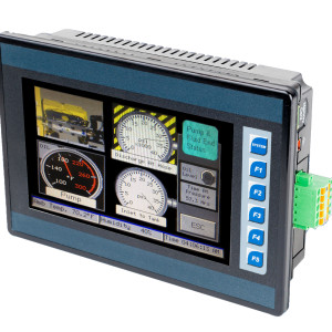
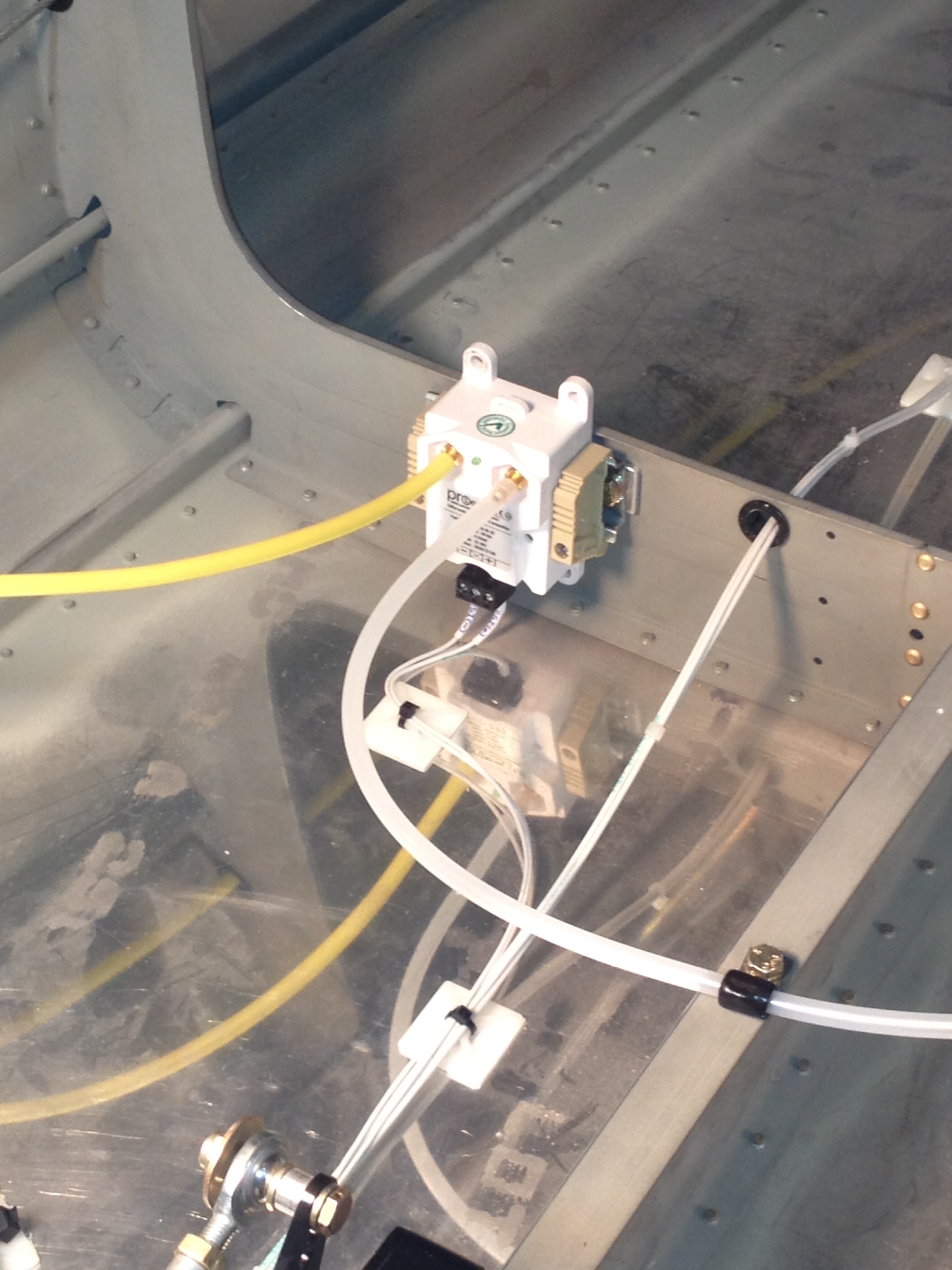
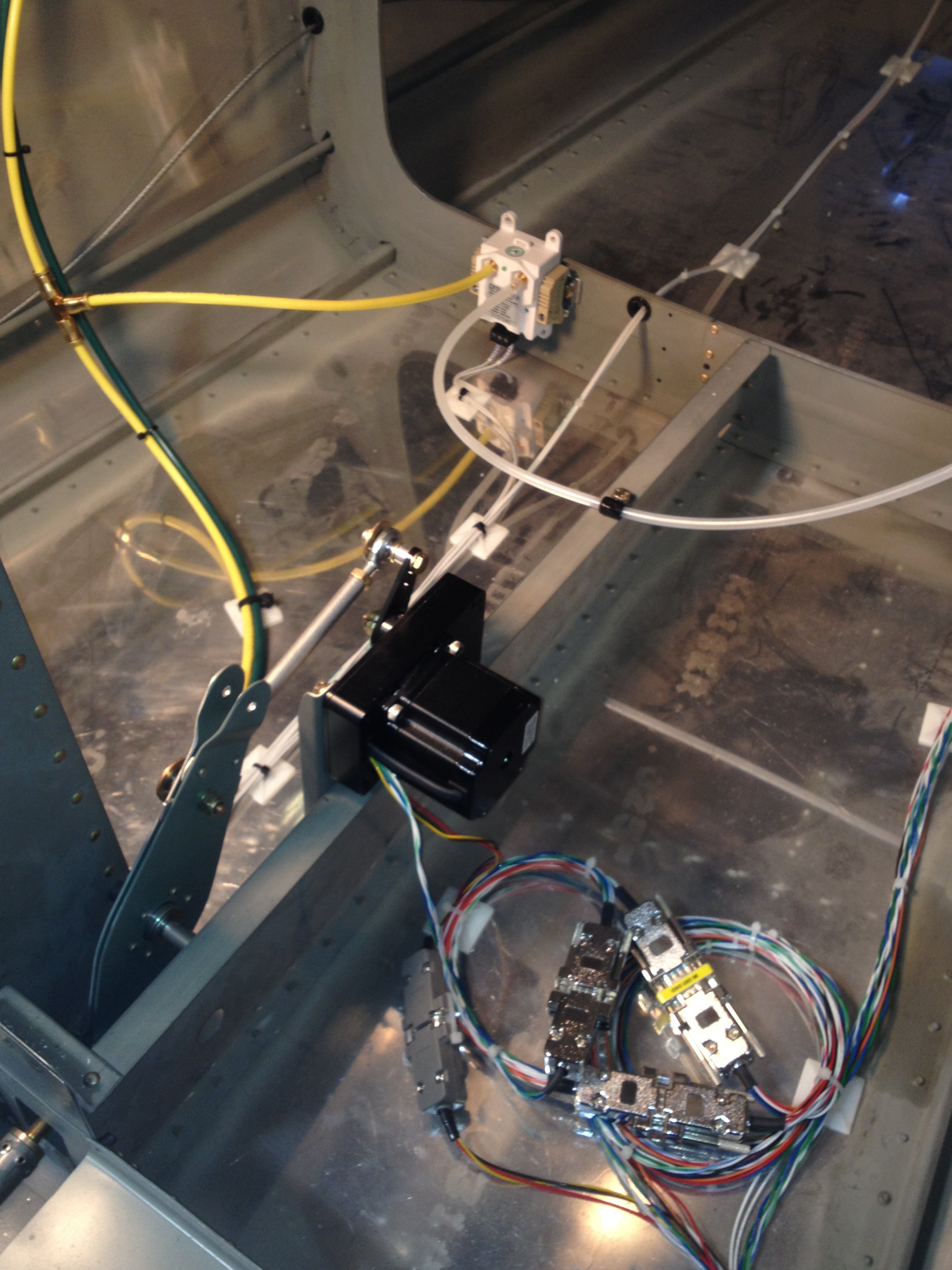
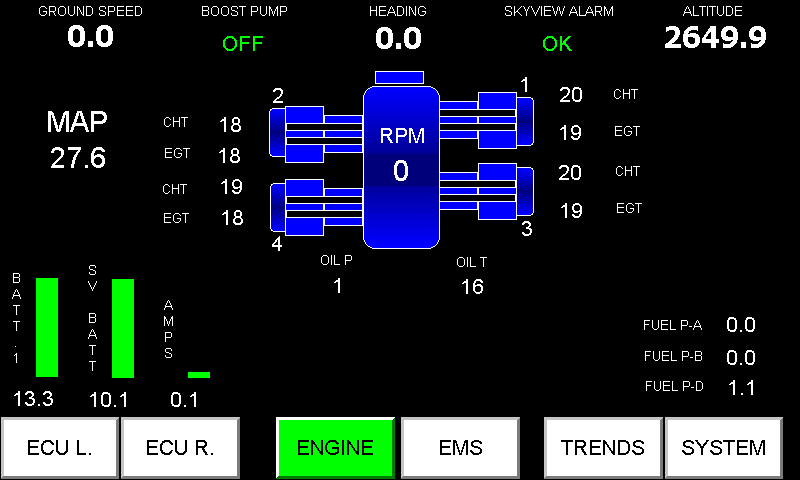
Present design interfaces to a GPS puck, the two Eagle ECUs and the Dynon serial data port. I also included a separate airspeed transducer to act as backup to Dynon. Its been a bit of work making it all come together over the last year. This unit will never replace a Dynon or Garmin for synthetic vision or moving maps but it does sweet work with trend displays and the handling of large packages of data. In the event of a Dynon failure, I can still safely fly and navigate my way to a safe landing site.The programming software which can be freely downloaded from the Horner website allows the user to program applications for whatever their creative minds desire. I’ll explain what I have done as time permits in future posts to this blog.
Here is a summary of the XL7 from the company web site:
- All units feature a high-resolution wide aspect ratio 7″ WVGA Color Touch Screen with 1000 nits of brightness. The innovative display provides high outdoor visibility and allows the XL7 to be used in a wide variety of ambient condition applications.
- Built-in digital & analog I/O with two 1MHz high-speed counters
- Dual 10/100 Ethernet for factory and world-wide networking adding flexibility when linking to factory networks like Modbus/TCP and Ethernet/IP, while performing standard functions such as: web serving, FTP file transfer, E-mail and protocol support.
- Dual CAN Ports for fieldbus flexibility. One port utilizes CsCAN for Distributed Plug and Play I/O over a 500m distance. The second port provides support for CANopen and J1939 for mobile applications
- USB 2.0 Ports for programming & FLASH drive support
- 32GB microSD Slot for Virtually Unlimited Data Logging
Its not my desire to market or prosper from what I am presenting here, just share what I have done and help you roll your own if you are so inclined.