TC4 Eagle ECU Monitor

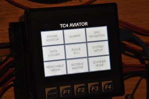
This is the latest release of the TC4 controller which is used to monitor, display and alarm on data and status from both of the Precision Airmotive Eagle ECUs (engine control units). The TC4 also has a GPS module which combines flight data with engine data for the best of tuning information. The data is stored in a micro SD memeory card. The TC4 has ethernet port, USB programming port, USB memory stick port and two serial ports for RS232 and RS485 communications. The pilot interface is a full color touch screen with impressive graphics and screen update times.
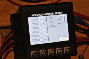
The TC4 communicates with both Eagle ECU A and ECU B via a RS485 Modbus data link. Each ECU is polled every two seconds and data is placed in the TC4 memory for processing. I have already bench tested the data link between the ECU and TC4 and now I am working on displays for all the various data types that are available. In addition to the GPS and Eagle ECU data, the TC4 can receive 4 analog inputs from various instruments, 12 digital inputs from switches or sensors and it has 6 relay outputs for driving lights or operating loads such as relays. The TC4 can also be expanded via its CANBUS port to monitor and control a large number of other devices which use this protocol.
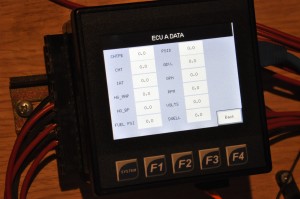
I will field test this controller in the CH701 prior to RV9A flight to ensure its screen design and operation is easy and intuitive to use.
Cowl access hatch

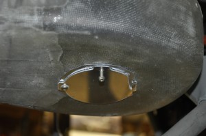
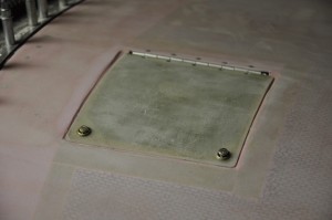
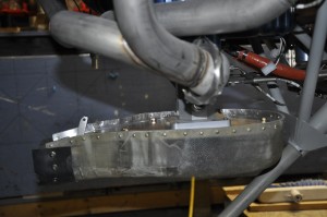
Another one of those simple tasks that I had been putting off. The cowl access hatch provides a means of successfully getting the top cowl piano hinge wire in and out of position (although I have yet to actually succeed at doing it) and provides access to the dip stick and oil filler spout. I have seen a number of variations of completing this task, some folks using hidden hinges and cool remote control latches, others by the book. I figured that anything but by the book is going to take three times as long as necessary and I am working to meet a first flight time of fall 2013, so from here on no trick stuff unless it really pays off in operation or maintenance. Anyways, this little door took about 6 hours from start to finish. The cam lock fasteners are about 1/8″ too long, so new ones will be stuck on the next aircraft spruce order.

Filter Air box wrap up

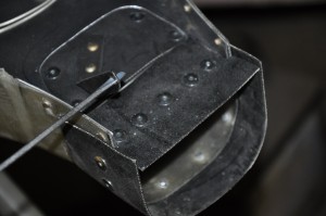
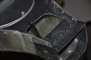
A somewhat simple asembly, the horizontal filter air box (FAB) took several hours and a couple of fibreglass sessions to complete. If you had a normal Airflow performance throttle body it would be an easier task as per plans,but with the eagle airflow performance throttle body, its overlength is about 1 1/2″ shorter. This places the inlet, which should line up with the cowl snout about 1 1/2″ too high. It appears that some folks solve this problem with aluminum or teflon spacers, I chose to modify the FAB by cutting it in two locations and making 2 bends to get it to the proper height. The alignment with the snout is perfect now and no spacers were required.

The FAB has an alternate air inlet which is cable operated from the cockpit. I am holding the lever forward to show the normal operating position. Should the air inlet snout become plugged (maybe a seagull found its way past the prop), I would pull the cable which would allow air from the lower cowl air to enter. The air still passes thru the air filter which is directly below the throttle body when the bypass is open.The rubber cowl seal material allows a good seal between the FAB and the inlet snout.


The last feature of the FAB is the airfilter bypass door. This is provided in case the air filter become plugged. Remember the seagull that got stuck in the snout lost a pile of feathers in the process and plugged the air filter. Another cable operated from the cockpit can be pulled which allows air to flow directly into the throttle body, maintaining power and flight. This bypass door must be reset from ground, assuming a very unusual event caused it to be opened.

I still have cables to install, which will happen once the rest of the firewall forward work is wrapped up.

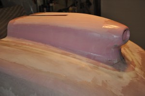
Engine cowl gets a vertical induction snout

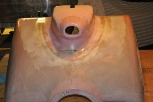
When I ordered my kit, I specified a 180 HP cowl in place of the standard 160 HP cowl. This was because I was planning on using the subaru engine for this project and it needed the additional room. I finally decided to not use the subaru engine and purchased a 180 HP IO360 with vertical induction. To make the horizontal induction cowl fit the engine, I had to order the vertical induction ram air snout. Last weekI  got to work grafting it onto the cowl. The task is pretty straight forward but takes time as one goes thru the glass, fill sand and fill and sand routine.Its getting close to being done and ready for prime, sand prime etc etc routine. I had forecast doing fiberglass work right to the end of the year (2012) and its looking like a pretty realistic plan.

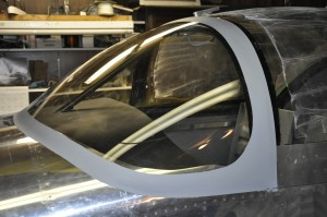
Wind screen trim and rear canopy skirt completion

It seemed that the filling and sand cycle would never end, but all good things must come to an end and so did this task. A few coats of high fill sandable primer and touchup with bondo scratch filler and I was finished with this piece. I know there will be another final touchup session before final paint goes on, but this is it for now.

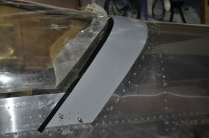
The rear skirt took an equal amount of effort to get to this stage of completion. I have yet to Sikaflex it into place (the black tape is the forward edge of the glue line) and flush rivet where it is attached to the canopy skirt. The fit between canopy and fuselage skin is great. Thanks to Bret Smith for his great building blog http://www.flightinnovations.com/ and ideas for completing the canopy attachment sequence.