Skyjeep engine upgrade finally complete

It seemed to take forever to wrap this engine upgrade up but its done now. The first start was amazing, fuel pump on, ecu power on, hit the starter and it burst to life in a few seconds. I quickly checked the BTDC notch with a timing light to confrm the 10 degrees I had set in the ecu was the real value it was reading and then got into playing with the mixture knob to get a smooth idle. Adjustment of the PSRU belt tracking followed and then verification of guages as it warmed up. The Air to Fuel ratio was not reading properly so I ignored it and played with the mixture adjust at a few power settings.
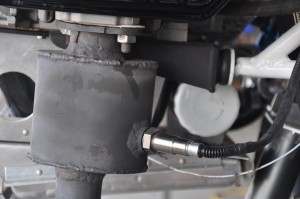
A bit more investigation on the A/F probe indicated that the standard unit I had installed had an effective range of 13.5 to 15. That range is of little use when tuning for power as I target for 12.5 A/F for max hp. A quick chat with Ross from SDS put me on the right track and I ordered a PLX wideband AF meter. This unit provides a range of 10 to 20 A/F readings with .1 A/F ratio accuracy. The sensor module has two analog outputs, 1 goes to the SDS controller and the other to an organic display module. Once installed I had a perfect indication of A/F ratio thruout the entire RPM range I use. One of the ECU contol parameters adjusted is the Fuel Number. This number is entered for every 250 rpm step from 500 rpm to 7000 rpm. You play with this number and fuel mixture adjust knob until you get a A/F ratio of 12.5 or so and a knob set at 12 oclock position which indicates zero mixture bias. Doing this task for the engine rpm range takes 30 minutes with the aircraft tied to a truck, prop on and engine under load. Its of no value to do this with the prop off.

This is a very quick summary of ECU setup, but she’s done and waiting for a chance to go flying and prove out the new engine. I also added 3 more degrees of pitch to the prop in anticipation of all the extra HP I will have available now.

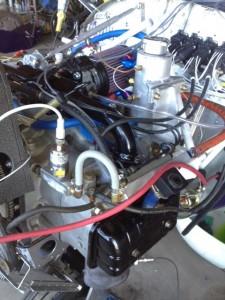
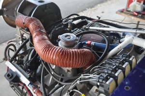
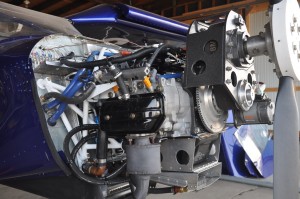
These pictures were taken before final cleanup was done. I’ll try and update these next time I am at the airport. I redid the copper sensing line for coolant pressure and ran it in the wire loom that goes back to the firewall.
Skyjeep upgrade motor mounts

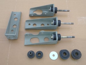
The original Reductions redrive motor mount bushings were due for a replacement. (they are shown in the bottom right corner of the photo)Easier said than solved as the bushings were custom units that could not be replaced. I opted to rework the metal hardpoints and use new isolator bushings from Barry Isolators. The units I selected had slightly different diameters but the same face to face measurements as the old ones which allowed the engine to sit in exactly the same position. I selected isolators that will support the load in all axis with a safety factor of 100%. The bushing are fail safe when you use the proper large diameter washers that Barry Isolators supplies. I used the 44001-13 isolators for this application.

I also had to enlarge the lightening holes on the top hard points to make room for the new fuel injectors and their electrical connectors. This took several file and test fit sessions to get a good fit with minimal metal removal.

Mar 2014 UPDATE: I have found that the 44001-13 isolators to be too soft in both the axial and radial loading conditions. After a few months the lower bushings which are under compression were squishing down way too much. My first flight this year was very interesting as the engine was moving to the right by a few degrees under load and hands off flight was not possible. Once power was reduced on final, the effects of this increased off set went away allowing a controlled final and landing.

I have ordered 4 new 22001-15 bushings from Black Diamond Industries. They have a 300# axial and 60# radial load capacity and the deflection VS load rating is 2.5 times better than the 44001-13.

I also ordered 4 22002-15 isolators which I may use for the bottom mounting points if the 22001-15 are still too squishy.


Skyjeep fuel system upgrade

The new fuel injected EA81 required a number of changes to the fuel and electrical systems of the CH701. The old engine had a carb and a pair of low pressure facet style pumps to deliver the fuel to the carb. The new engine requires a pair of high pressure fuel pumps, a pair of 10 mircon filters down stream of the pumps and a fuel return line to the header tank from the fuel rail pressure regulator.

I was advised to use the Walbro HP fuel pumps. These pumps are recommended for reliability and ability to pull fuel better than Bosch pumps. Fitting one gascolator, two fuel pumps, two filters and all the required fitting needed to facilitate maintenance of these items makes for a real head scratching installation. It took three four hour sessions out at the hanger to get it the way I wanted. I haven’t had to maintain it yet, so filter pulling will be the ultimate test.

The return fuel line uses a fire sleeved fuel hose, steel bulkhead fitting and 1/4″ steel tubing for the loop back to the header tank. This is a low pressure loop which dumps excess fuel back into the header tank as the fuel rail regulator does its thing to keep the rail at 36 psig.

I used a firesleeved stainless steel braided fuel line between the fuel pump system on the firewall and the fuel rail inlet. This was a surplus hose that came with my RV9A firewall forward kit.

I added a fuel pressure transducer on the fuel rail and a digital gauge in the instrument panel for monitoring fuel pressure. This transducer is ranged for a 0-100 psi and puts out a 4-20 ma signal which is displayed on a digital display.

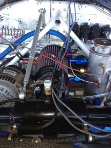
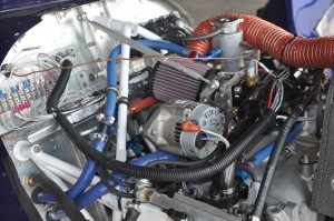
The photo on the left shows the new intake manifold, throttle body and filter assembly. To the right of the air filter is the new swirl pot for the coolant system. This pot collects the hot water from the two head outlets and directs it to the cabin heater and eventually back into the water pump or when water temp reaches 180 deg.f the thermostat in the bottom of the swirl pot opens and send the hot coolant off to the belly mounted radiator. The copper sensing line on the pot will be removed and reworked prior to signing off the upgrade in the log book.

Sky Jeep gets an overhaul

The CH701 which I have been flying since 1999 was long overdue for a fresh engine. The original subaru ea81 engine was starting to loose compression in two cylinders, the oil was coming out too dark when changed and oil pressure was way too low to ignore when flying. Last few flights in January, I found myself give the oil pressure guage more attention than I should. I grounded myself and starting looking for a fresh engine.

In May I found an engine at Ram Performance in South Carolina which had been “zero” timed by Ram’s owner Ron. It was not one of his latest rebuilds but rather one which had gone out to a customer, sat for a few years and then came back to Ram as part of a trade up to a newer package. Ron went thru the engine when it came back and was deemed to stil be zero time. The engine was backed up with a warranty, so I paid up and waited for its arrival.

The engine was pretty much as promised and was in almost fresh condition. Only problem noted was a broken bracket that holds the fuel rail to the head. Ram offered to replace it but I opted to make a new pair of brackets out of some 1/8″ 4130 plate and 1/2″ square tube. There were a number of nuts with nylon locking collars used in the Ram rebuild along with non-AN type bolts. As these types of locking nuts should not be used in an engine compartment, I replaced where necessary with AN hardware with steel locking nuts.

The new EA81 engine has a number of performance enhancements like fuel injection, electronic ignition, special grind cam, stainless steel valves and HD valve springs. This work provides an EA-81 which produces 115-118 hp on the RAM dyno. This engine delivered 118 hp when tested. The engine it is replacing was not likely making more than 90 hp so the increase of 28 hp should be quite notable.

The engine came with a Real World Solutions EC2 fuel and ignition controller. The controller is pretty basic and has no user interface. The EC2 controller has been popular with the Mazda rotary crowd and a number of Subaru conversions have used this ECU. When I started working on the engine, I discovered some poor electrical work had been done on the EC2 connections. A few wires pulled out of the LS1 spark coils with a slight tug and further digging into the wiring revealed a lot of really bad solder joints. My confidence in this part of the rebuild slid pretty low when I found these items. Rather than rewire the EC2 controller, I pulled the electrical components, 58 tooth flywheel and pickup assembly and put them in a cardboard box. Maybe I’ll find another project that can use this EC2 package but it was not going to be this one.

Fortunately I had a new SDS engine controler package sitting on the shelf which I could use for this upgrade. I had originally purchased the SDS package from Simple Digital Systems for a EJ25 engine I was going to install in my RV9A project. I ended up installing a new ECI IO360 engine and did not require the SDS package. So long story short, I installed new Hall Effect pickup in the rear lower pully and a made a few more modifications to the installation to accomodate inlet air temperature sensing and coolant water sensor. The SDS ECU package is high quality product and I have a lot more confidence flying with this system in place. I guess if you don’t have something to compare an EC2 package with you might not know what a difference there is.

Sika Flex holds it all together

For a variety of reasons, I have decided to stray from the standard Vans method of attaching the canopy and windscreen to their respective frames. I know its a time tested procedure and there are thousands of RVs flying that have been built this way. I also know that the extreme temperature swings we see up here in Canada will test the limit of the polycarbonate and steel tube frame bond when a rivet is used. The polycarbonate will be the one who gives and resulting stress cracks will inevitably appear. It happened on my CH701 and it will happen on the RV9A.

Vans chose to drill and then rivet the canopy to the frame and side skirts. I have decided to glue the canopy to the frame using a modern adhesive system based upon the product called Sikaflex 295UV. This product is used extensively in the marine industry for attaching windows to frames in a wide range of boats, ships etc. The product is UV stabilized and available in either white or black color. The tubes of Sikaflex 295UV can be purchased from a variety of marine retail outlets. It is time limited (best before) so most dealers don’t keep it on the shelf and have to order it in for you. The most expensive part of this process is the primer product and cleaner product that must be used to prepare the parts to be joined.

I am not breaking new ground using Sikaflex, many others have taken this path. I relied on a number of other builder’s web sites to get the process straight in my mind. A good place to look is Bret’s RV9A builders log under the canopy posts. I checked back with Bret in January of 2012 to see how the Sikaflex was holding up and he reported that it was as good as new after 3 years and a couple hunderd hours of flight. I have heard of a few problems during the preparation phase of this task with cleaner getting somewhere it was not supposed to be and fogging the surface of the canopy. This would be remedied by taking care during the application of the prep solutions and protecting the surfaces where you don’t want it to go.

UPDATE

The summer has passed and I have failed at keeping my building log current. Too much to do on the ranch this time of the year plus a new engine upgrade in the CH701 made for little log update time.

I did manage to finish attaching the canopy to the frame with Sikaflex and completed the attachment of the canopy skirt and canopy latch system. The canopy turned out great, slides freely in the tracks and locks nicely in place. The rear canopy locking pins are a bit tight in the delron blocks but that will loosen over time so no worries there. I must now make sure I have completed every task I can think of forward of the instrument panel so the forward cabin skin can be riveted in place. Once in place, any work forward of the instrument panel becomes an upside down task, not particularly fun.

I’ll post a picture of the finished canopy work shortly.