Polishing Techniques – Compounding

There are two techniques used in the aluminum skin polishing, the first being compound polishing and the second being orbital.

Compound polishing uses a circular wool buffing pad on either a 3/4″ variable speed electric drill or a made for purpose low speed polisher. The two things most desireable in this process are speed control and power. The 10 inch wool pad can use up a fair bit of power and you need a place to put both your hands when you are compounding so forget about using a 1/4″ drill.IMG_0348 
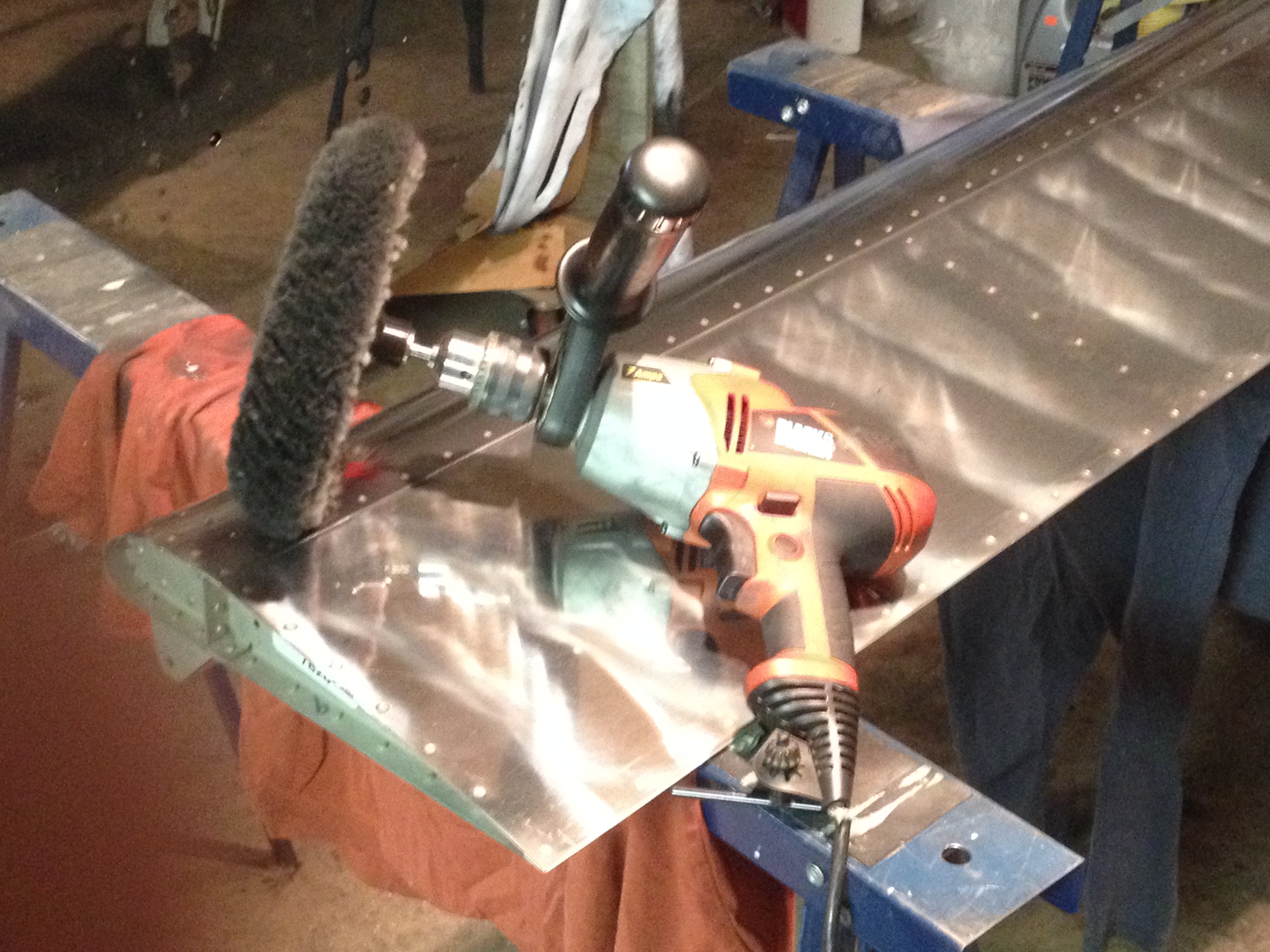
I used an older Black and Decker polisher for a while for the wing surfaces. It has too high of a speed, >2000 rpm so its not the best when doing smaller parts or working around brackets and hinges. I got into using a Black and Decker 3/4″ drill which has a beefy side handle. It had become my tool of choice for compounding.

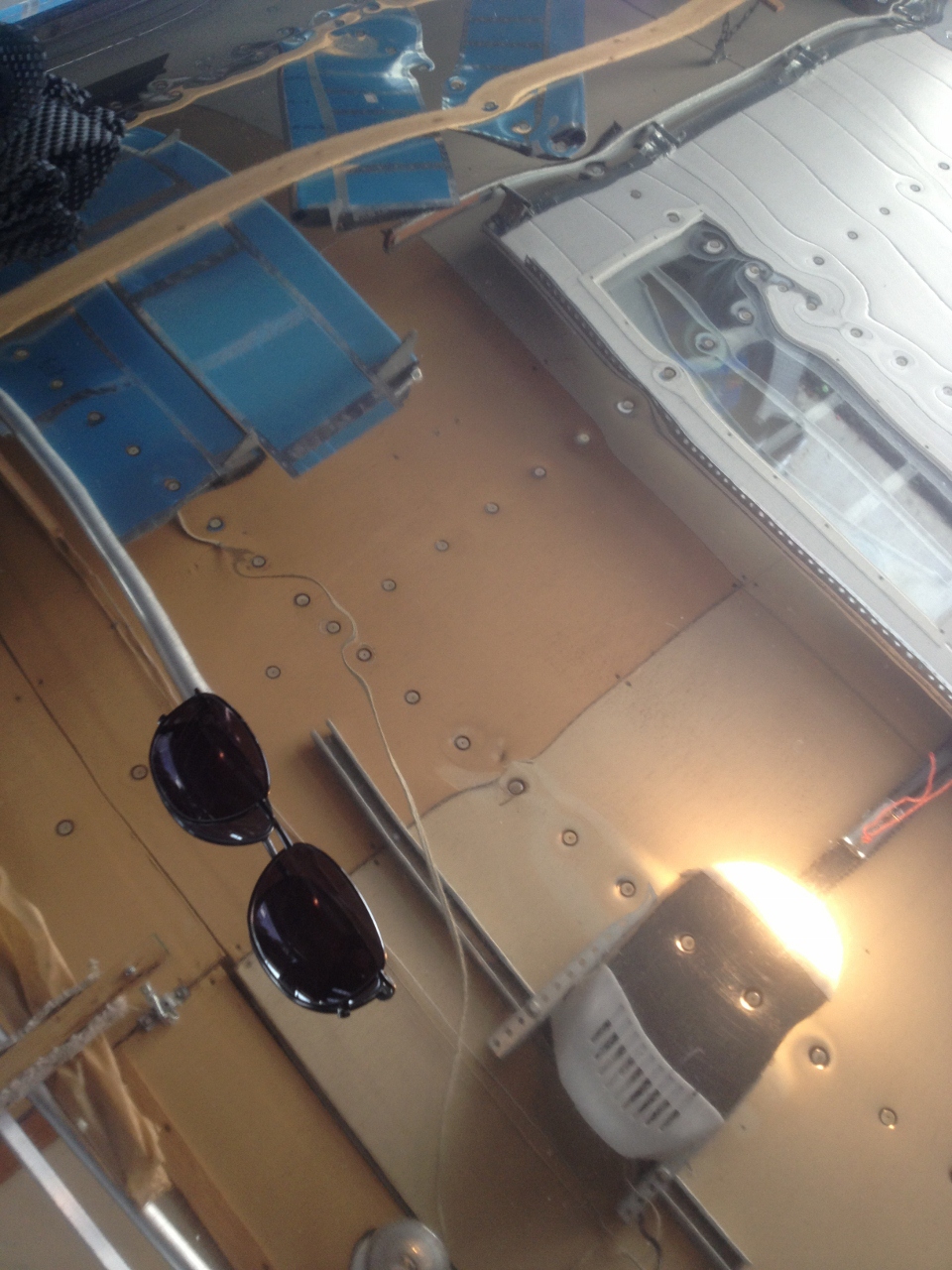
Compound polishing is used to remove the mill marks from the metal, smooth out scratches and generally prepare the metal for the fine polishing to follow. The polisher is drawn across (or down) the surface in one continious action. No back and forth or circle motion allowed. You can see in the picture above, the swirl lines left across the surface of this flap. These are removed in the next step with the orbital polisher.


Polishing the RV9A

I waviered back and forth on the subject of exterior finish. For a while I thought I was going to turn one of the greenhouses into a paint booth and paint the RV white and red. The greenhouses turned out to be way too hot for painting and waiting for cool weather would push the painting season into the fall months if I was going to be able to manage the finish.

Throughout the build, I kept the concept of total polish with color trim on the fiberglass parts in my mind. I preserved the skins as much as possible, leaving the protective blue plastic in place until the very end. I read the Vans Airforce polishing forum several times and the thought of polishing didn’t scare me off. I found the Perfect Polish web site after reading about it on the Vans site several times. This turned out to be a good source of both materials and information.

IMG_0318 (960x1280)So I took the plunge and decided to try this polished metal finish on my project. So far, its been a very rewarding process. The polishing skills have developed now to the point that I know what I am doing and how to adjust these techniques to various metal conditions as I come across them. In this section of the Werks, I will attempt to pass on what I have learned about polishing a metal airplane. There is a lot of knowledge out there on the subject and as a newbie to this process I hope to pick up more tricks and skills that will reduce the polish time and increase the shine factor.

If you haven’t figured it out, my sun glasses are sitting on the polished wing and the ceiling full of aircraft parts is reflected into the camera.

Back to building, the interior arrives

Its been way too long since my last blog update. Summer happens and shop time goes to zero around our place. I built a new 60’x40′ shop this summer and it consumed just about every free day I had. There wasn’t even any bad weather that would allow me to retreat to the shop, day after day of nice sunny weather all summer long.

IMG_0324We ordered a new interior from Classic Aero Designs out of Oregon. We picked the all leather Sportsman line with a color combination that would look sharp and not date itself in 5 years(we think so anyways). When I placed the order, they said it would take 12 weeks until my order would be completed. That time estimate was pretty accurate the multiple boxes showed up mid September. The package included carpet front and back, seats, side panels and complete covering in the baggage area.IMG_0325 I spent a half a day fitting the pieces in a semi permanent manner. Most parts will have to come out again for final assembly and inspection so I didn’t worry too much about getting it completed to perfection.IMG_0326

A full ballon in the morning is a good thing

leaktestI forgot to leak test the right fuel tank so figured I better get it out of the way before I discover a leak the hard way (full tank of fuel). The fuel line fittings are capped, a tire air stem is installed in the drain fitting and a balloon is taped to the tank vent line fitting. The ballon limits the pressure allowed in the tank to a safe limit under 1 PSI. I used packing tape to seal the tank fill plug. If all goes well, the ballon should look like this for 24 hours. I was please to open the garage door this morning and find my balloon full of air, roughly 24 hours after it was inflated.

Work has been progressing slowly, little bits and pieces where I can grab an hour or two. Green house season is wrapped up so more time should come my way over the next few months for the project.

I am planning to set a greenhouse up as a paint booth this month. I have lots of vent fans so it should be easy to keep a good flow of air going thru the house when the paint work starts. A buddy who painted my 701 years ago has agreed to help me get this job done so here goes another learning adventure.

Wings are off the fuselage now and the garage is not as difficult to navigate around in, Time to fit the fibreglass around the horizontal stab and vertical stab.

Rear Spar Attachment

The drilling of the rear spar bolt holes is the final step in wing attachment process. Once these holes are drilled, the sweep and incidence is locked in. An error in the drilling of this hole would result in a whole lot of schedule slippage due to rework on both the fuselage and wing structures to replace the misdrilled components. The hole must be located to provide a minimum of 5/8″ edge distance from the centre of the hole on all rear spar attachment components. It also must be drilled perpendicular to the rear spar stubs, which is tricky as all surrounding components and edges are at a variety of angles.

I used a 5/8″ spacer to draw lines on the rear spar tab to establish my boundaries. This provided me with a 1/8″ box to locate my hole in. I drilled a shallow indent inthe centre of this box and then used a drill guide to maintain a perpendicular drill angle for the first pilot hole (1/8″). I repeated this procedure, using a drill guide as I opened the hole up to final size of 5/16″ in steps of 3/16″, 1/4″ then 5/16″. This worked well for both left and right wings.

I then moved on to the fitting of the gap seal strips where the wing intercepts the fuselage and the drilling of the holes in the bottom wing skin where they overlap the fuselage lower skin. These holes will be opened up to final size, dimpled, countersunk and nut plates installed once the wings are removed from the fuselage.

I am happy I was able to get the wings on the fuselage and work thru this stage of the build without having to move the aircraft outside. The weather has been very active for the last three weeks which would of likely pushed me into working too quickly and perhaps screwing something up in the process.