The Engine and Flight Systems Manager Intro

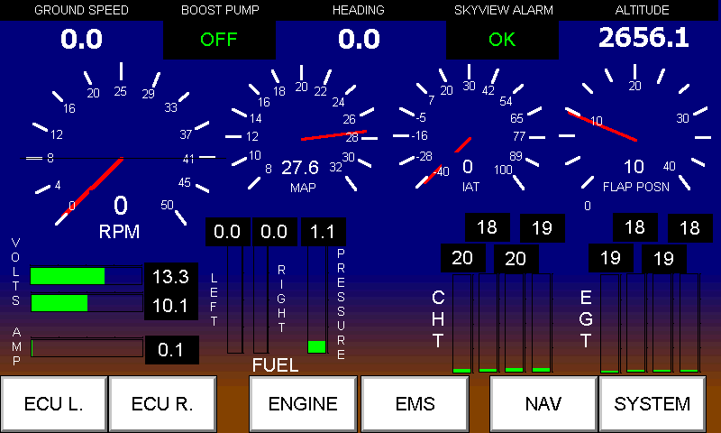
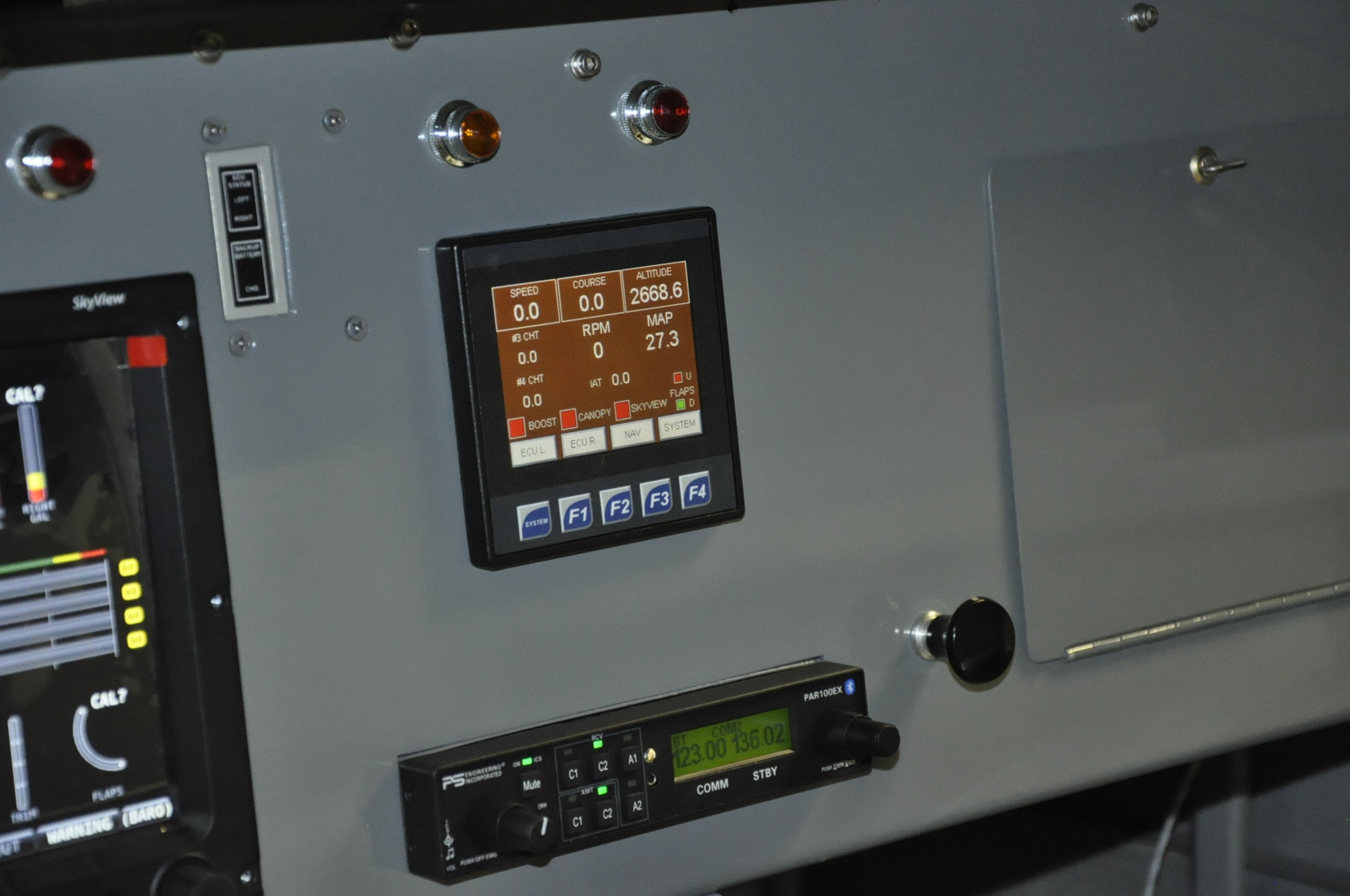
What started out as a small 4″ monocolor display has grown into a high resolution color touch screen display with super bright graphics. It has a brightness rating of 1000 nits which is slightly lower than the 10 inch Dynon Skyview it will be sitting beside in my panel. I have custom built all the displays and logic programs that provide a list of features I’ll try and explain in upcoming posts. The main drive for building this display was to set up a better interface to the Precision Eagle ECU than what was delivered in the box. If you have an Eagle, you know what I mean. This system communicates with both the left and right ECU via a communications driver I configured. This system also receives Skyview Engine Monitor data via a serial data link. Updates are every second. Final interface is with a Garmin GPS module for back up position data and some basic navigation features with a destinations data base. There are many more features built in that I will expand on as web time allows. This is not a commercial venture, just something I crafted for my project and I will share with others who have similar needs.MAIN_SCREEN


Flap Position Feedback

Yes, its been a long break from the build, every year Christmas and getway trips take their toll on the building process, but what the heck, its a hobby not a job, right?

Before Christmas I finished adding a flap position sensor system. I did mine a little different than the other examples I have seen on the web. I used the standard Ray Allen position sensor which is a linear motion potentiometer of 0 to 4k ohms. The circuit uses a regulated 0-10 volt source and I use 10 volts as my 0 degree setting and 0 volts as my 40 degree setting. If the circuit has a problem, I’ll know right away when my flap position indicates 40 degrees. I used a .5 inch travel sensor in place of the usual 1 inch travel model. I used a couple of links to divide the motion of the flap actuator in half and linearize the travel/voltage reading as much as possible. It took a bit of trial and error to get the links length correct but I’m happy with what I see now as an indicated position on the TC7 Engine and Flight System Manager (EFSM). That’s the new accro dreamed up for the new box I have created for the panel. More on that in subsequent posts.Picture 003 Picture 002

Instrument Panel almost done

Eagle ECU Interface and Par100EX Radio

Eagle ECU Interface and Par100EX Radio

Its been a long time since the last RV9A building update. I have been working away at a steady rate, completing the electrical work in the cabin area. The Eagle ECU interface is working well, communicating with both left and right engine control computers and a Garmin GPS module. I built a backup navigation system into this interface which works really well when you fly east but when you fly west the heading indication gets screwed up. I’ll work at debugging that little issue when more time is available for doing those optional tasks.Inst Panel 3I finally broke down and ordered the 10″ Skyview display in late February. The Loonie was loosing strenght against the USD and the cost of the display was increasing on a daily basis. The cutout in the panel which was made a year ago fit perfectly along with the six mounting holes. The Skyview is a great Primary Flight Display, Engine Monitor and moving map package. I will also order the transponder module next year once the 40 hours of flying in a 25 NM circle are done and I have the need to fly into busier airports.

10" Skyview in split mode

10″ Skyview in split mode

The final cool item is the PS Engineering PAR100EX Radio and Intercom package. The Panel Faceplate has the intercom controls on the left side and radio controls on the right. The actual radio is a Microair 760 transciever which is attached to the bottom on the map box. Cool thing about the Intecom is the Blue Tooth interface which allows me to  connect to my IPhone for music and making/receiving telephone calls. The Lightspeed headset works very well for making the calls, clear on both ends.I still have to get the laser cut labels made for all the switches, knobs and dials. These will be done by Dave at Dave’s Woodcraft in Stettler. He did my 701 labels 15 years ago and they are still looking great.

Back in the cabin again

Cabin diving I have completed a number of under the cowl tasks, installing the rest of the Vetterman exhaust system, wiring the alternator and starter and installing the cabin heat system. Time to take a break from that area and work in the cabin again. The instrument panel still comes out to allow acess to the wiring terminals on the bulk head. I have powered the electrical system up and verified my wiring is as per my drawings. Some red lines were required and I will update the computer files next time I am doing drawing updates. I am going to install my new PS Engineering PAR100EX radio now. The panel goes to the kitchen table where I can sit and relax while I do the wiring of this system. My wife is out of town for a few weeks so I can get away with leaving a mess on the kitchen table till this wiring task is done.

TC4 Eagle ECU Monitor

This is the latest release of the TC4 controller which is used to monitor, display and alarm on data and status from both of the Precision Airmotive Eagle ECUs (engine control units). The TC4 also has a GPS module which combines flight data with engine data for the best of tuning information. The data is stored in a micro SD memeory card. The TC4 has ethernet port, USB programming port, USB memory stick port and two serial ports for RS232 and RS485 communications. The pilot interface is a full color touch screen with impressive graphics and screen update times.

The TC4 communicates with both Eagle ECU A and ECU B via a RS485 Modbus data link. Each ECU is polled every two seconds and data is placed in the TC4 memory for processing. I have already bench tested the data link between the ECU and TC4 and now I am working on displays for all the various data types that are available. In addition to the GPS and Eagle ECU data, the TC4 can receive 4 analog inputs from various instruments, 12 digital inputs from switches or sensors and it has 6 relay outputs for driving lights or operating loads such as relays. The TC4 can also be expanded via its CANBUS port to monitor and control a large number of other devices which use this protocol.

I will field test this controller in the CH701 prior to RV9A flight to ensure its screen design and operation is easy and intuitive to use.