Glove box building

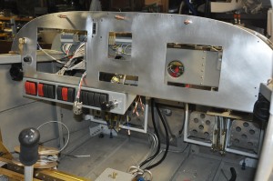
This week I hope to build and install a glove box in the instrument panel. The glove box will occupy a large cutout that was made for a future glass panel screen. If after flying off my first 40 hours, I find that the 10 inch screen does not display all the data I need to safely fly the aircraft, I’ll pull the glove box out and slip the second 7 inch screen in. Its that simple. I also have made provisions for power and network connections for the second screen.

I completed all the metal work for the glove box last night. Its a simple cube made of 6061T6 aluminum .025 thick and 032 thick on the bottom surface. Dimensions are approx 7″ square. I plan to install the two communication ports for the Eagle ECUs (left and right) in this box, along the forward surface. Normally the engine monitor will poll data from these ports but if necessary, I can disconnect the engine monitor and connect a lap top to the desired ECU port.

Should be able to pack a good sized lunch and camera away in it.

Instrument Panel Cutouts

I decided to go with a PS-Engineering radio and intercom package, the PAR100. Its a nice compact package that only needs a cutout 1.3″ tall and the standard radio stack width of 6.25″. That eliminated the need for a separate intercom in the comm stack. The next item to consider was the transponder. Dynon includes a transponder option for the Skyview system. The transponder is accessed via the Skyview screen so a panel cutout is not necessary for the transponder face plate. The transponder box is remote mounted and takes power from a dedicated circuit. I made cutout on the right side of the panel for a future 7″ Skyview display screen. For the time being I will build a glove box in the cutout hole. If and when I need the second screen, I’ll remove the glove box and slip the panel in.

All the panel cutouts were done with a jig saw and a bosch metal cutting blade. It worked very nicely on this 2024 aluminum. Finished up the cutouts with a few different file cuts.

I installed the Eagle ECU annunciator just right and above the 10″ Skyview Display. I installed the mixture adjust knob just to the left of the 10″ Skyview display.

Bare Instrument Panel

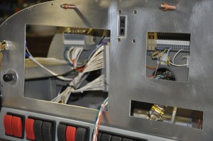
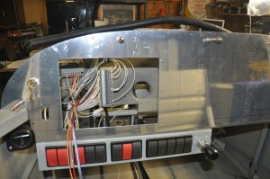
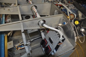
Looking into the panel, large cutout on the left for the 10″ Skyview Display. All switches across the bottom of the panel infront of the pilot. No breakers on the panel, all circuits protected by fuses installed in the Power Distribution modules (2) which are located on the right side of the firewall, above the passenger’s feet. The wiring behind the panel is still loosely gathered and messy. It will be cleaned up and wrapped tight once all the wires are in the bundles. In the left photo you can see the power distribution modules. They hold a total of 20 fuses and 10 relays. The modules are on a hinged door that swings up and latches. The wiring bundle to the loads travels across the fuselage in a cable tray

Finished up EGT and CHT wiring, installed shunt

Today I completed the connection of the thermocouples to the Skyview harness leads. Pretty easy task, strip crimp shrink assemble, repeat six times. Installed the ammeter shunt upstream of the alternator fuse block. Ran leads from the Skyview harness down to the shunt terminals. Those tasks used up the morning and left the afternoon for snow clearing and whatever. It was warm and the sun was shining, perfect outdoor job weather. 

Engine Sensors

I received the Dynon engine sensor package for my engine earlier this week. The thermocouples for the EGT and CHT appear to be well made, not quite industrial quality I am used to but will not see as severe as service so not worries here. There are two large multiconductor cables in the package, one made of thermocouple extension leads and the other made of 37 – 22 guage wires. I was wondering if I would be able to get all the required T/C leads and sensor leads thru the remaining space in the SafeAir1 firewall passthru. Turned out that there is still room to spare if I need to run any more wires up front.
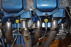
A small problem became apparent earlier this week when it dawned on me that the Eagle ECU needs two CHT measurements (#3 & #4 cylinders) and the Skyview needs all four. I am working on a couple of ideas to address this problem. 1- replace the existing CHT thermocouples with dual element thermocouples then each system can have its own temperature element or 2 – find a way to pass the data from Skyview into the Eagle display screen. Number 1 is easy, number 2 is a challenge.
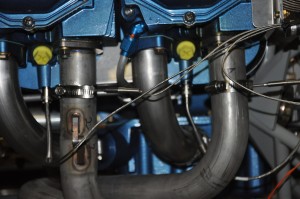
I drilled the 1/8″ holes in each of the exhaust pipes, 2″ down the pipe (measured from the flange). I made sure that the EGT T/Cs would not interfere with spark plug removal or be close to the cowling. Installation is pretty easy, clean the hole and slip the T/C into the hole and tighten up the SS hose clamp. The CHT T/Cs were about as easy, just screw the bayonet adapter into the 1/8″NPTF threded hole under the bottom spark plug.

The Fuel pressure and oil pressure transducers simply thread into the Vans 3 port manifold block. Braided hoses and plugs for the unused port holes finish the job. The room is pretty tight under the engine mount frame but nothing touches or rubs.
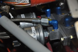
The manifold pressure transducer goes on the cool side of the firewall. I had a Vans manifold pressure kit in the firewall forward package. It is comprised of a AN fitting that goes in the #3 cylinder intake port (another 1/8″ NPTF hole), a long length of braided hose and a bulkhead fitting. The transducer will be mounted on the bulkhead forward of the instrument panel and connected to the bulkhead fitting with tygon tubing.

The ammeter shunt will be mounted just under the alternator fuse block. I’ll hopefully finish that up tomorrow morning.
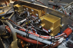
The upper firewall is really filling up with stuff. It will be a challange to keep it looking neat and organized.

Overall, a good project day, focused building with no distractions and as a bonus, three dog walks down the creek and thru the bush. The -30 cold snap finally broke and even -15 felt warm. Thats pretty bad eh?