Looking into the panel, large cutout on the left for the 10″ Skyview Display.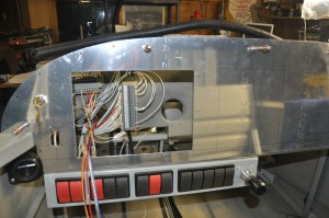 All switches across the bottom of the panel infront of the pilot. No breakers on the panel, all circuits protected by fuses installed in the Power Distribution modules (2) which are located on the right side of the firewall, above the passenger’s feet. The wiring behind the panel is still loosely gathered and messy. It will be cleaned up and wrapped tight once all the wires are in the bundles.
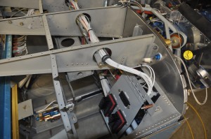 In the left photo you can see the power distribution modules. They hold a total of 20 fuses and 10 relays. The modules are on a hinged door that swings up and latches. The wiring bundle to the loads travels across the fuselage in a cable tray
Finished up EGT and CHT wiring, installed shunt
Today I completed the connection of the thermocouples to the Skyview harness leads. Pretty easy task, strip crimp shrink assemble, repeat six times.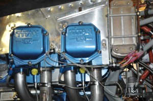 Installed the ammeter shunt upstream of the alternator fuse block. Ran leads from the Skyview harness down to the shunt terminals. Those tasks used up the morning and left the afternoon for snow clearing and whatever. It was warm and the sun was shining, perfect outdoor job weather.
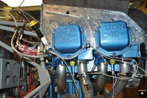
Engine Sensors
I received the Dynon engine sensor package for my engine earlier this week. The thermocouples for the EGT and CHT appear to be well made, not quite industrial quality I am used to but will not see as severe as service so not worries here. There are two large multiconductor cables in the package, one made of thermocouple extension leads and the other made of 37 – 22 guage wires. I was wondering if I would be able to get all the required T/C leads and sensor leads thru the remaining space in the SafeAir1 firewall passthru. Turned out that there is still room to spare if I need to run any more wires up front.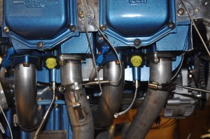
A small problem became apparent earlier this week when it dawned on me that the Eagle ECU needs two CHT measurements (#3 & #4 cylinders) and the Skyview needs all four. I am working on a couple of ideas to address this problem. 1- replace the existing CHT thermocouples with dual element thermocouples then each system can have its own temperature element or 2 – find a way to pass the data from Skyview into the Eagle display screen. Number 1 is easy, number 2 is a challenge.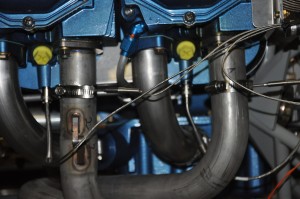
I drilled the 1/8″ holes in each of the exhaust pipes, 2″ down the pipe (measured from the flange). I made sure that the EGT T/Cs would not interfere with spark plug removal or be close to the cowling. Installation is pretty easy, clean the hole and slip the T/C into the hole and tighten up the SS hose clamp. The CHT T/Cs were about as easy, just screw the bayonet adapter into the 1/8″NPTF threded hole under the bottom spark plug.
The Fuel pressure and oil pressure transducers simply thread into the Vans 3 port manifold block. 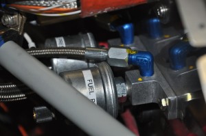 Braided hoses and plugs for the unused port holes finish the job. The room is pretty tight under the engine mount frame but nothing touches or rubs.
The manifold pressure transducer goes on the cool side of the firewall. I had a Vans manifold pressure kit in the firewall forward package. It is comprised of a AN fitting that goes in the #3 cylinder intake port (another 1/8″ NPTF hole), a long length of braided hose and a bulkhead fitting. The transducer will be mounted on the bulkhead forward of the instrument panel and connected to the bulkhead fitting with tygon tubing.
The ammeter shunt will be mounted just under the alternator fuse block. I’ll hopefully finish that up tomorrow morning.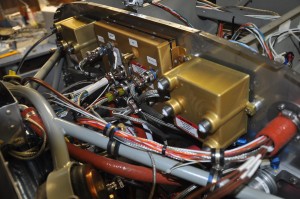
The upper firewall is really filling up with stuff. It will be a challange to keep it looking neat and organized.
Overall, a good project day, focused building with no distractions and as a bonus, three dog walks down the creek and thru the bush. The -30 cold snap finally broke and even -15 felt warm. Thats pretty bad eh?
Control Stick terminal block (TB3)
I installed a Ray Allen stick grip which has 5 buttons in the head of the grip. Two buttons are assigned to the elevator trim control (up and down trim), one is for Auto Pilot Dis-engage command to the A/P servos, one is for a relay which will be used to initiate a command selected in the on board programmable controller (such as start or stop camera recording, start smoke system etc) and the last is the Push to Talk button for radio communications. I brought these wire out to a terminal block which is located below the pilots seat.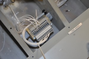 I used the WAGO spring clamping series terminal blocks everywhere I need to provide a junction point. These terminal blocks are designed for high vibration service and do not loosen up like screws do over time. Additional terminals are provided for the flap actuator connections.
Back to wiring
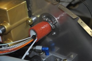
It was time to take a break from the baffle work and work away at the endless wiring chores. Since my last update, I completed the majority of the Precision Fuel and Injection system wiring. First task was to complete the install of the SafeAir firewall penetration kit. This kit allows you to pass all your wiring thru the Stainless Steel firewall and protect the wiring from damage due to vibration or cuts on the razor sharp stainless steel. 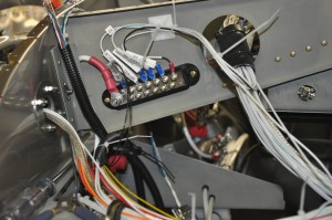 Once completed and sealed, the flames of an engine compartment fire will have to find a different way to burn my toes. heres a couple of shots of both sides of the firewall prior to sealing step. On the top photo the wiring passes into the engine compartment thru a nicely radiused flange and tube. The bottom photo shows the wiring entering the engine compartment thru a fire sleeve which will be finished off with additional firesleeve and stainless banding when I’m sure all the wiring is complete.