Rear Spar Attachment

The drilling of the rear spar bolt holes is the final step in wing attachment process. Once these holes are drilled, the sweep and incidence is locked in. An error in the drilling of this hole would result in a whole lot of schedule slippage due to rework on both the fuselage and wing structures to replace the misdrilled components. The hole must be located to provide a minimum of 5/8″ edge distance from the centre of the hole on all rear spar attachment components. It also must be drilled perpendicular to the rear spar stubs, which is tricky as all surrounding components and edges are at a variety of angles.

I used a 5/8″ spacer to draw lines on the rear spar tab to establish my boundaries. This provided me with a 1/8″ box to locate my hole in. I drilled a shallow indent inthe centre of this box and then used a drill guide to maintain a perpendicular drill angle for the first pilot hole (1/8″). I repeated this procedure, using a drill guide as I opened the hole up to final size of 5/16″ in steps of 3/16″, 1/4″ then 5/16″. This worked well for both left and right wings.

I then moved on to the fitting of the gap seal strips where the wing intercepts the fuselage and the drilling of the holes in the bottom wing skin where they overlap the fuselage lower skin. These holes will be opened up to final size, dimpled, countersunk and nut plates installed once the wings are removed from the fuselage.

I am happy I was able to get the wings on the fuselage and work thru this stage of the build without having to move the aircraft outside. The weather has been very active for the last three weeks which would of likely pushed me into working too quickly and perhaps screwing something up in the process.
Wing Alignment

Spring rains mean no yard work which equals more quality shop time!

I leveled the aircraft using the main spar in the cabin and upper longerons as reference lines. The tail had to come up several inches to reach level. I used a pair of bottle jacks and a padded timber under the fuselage to achieve this. The nose wheel remained chocked in place to keep the airframe somewhat stable.

First check completed was a diagonal measure from each wingtip to aft end of fuselage. Each measurement was was exactly the same, 15 feet 1/4″. That was a good indication that the wings were perfectly aligned.

Next check is to confirm zero or at least minimal equal sweep on both wings. To complete this check I dropped four plumb bob lines from the leading edge of the wings, two outboard and two inboard. A chalk line stretched from the plumb bob at each wing tip provides a reference line. The two inboard plumb bobs touched this reference line. This confirmed zero sweep and perfect diagonal alignment with the fuselage. These Van’s kits are absolutely awesome, put together a pile of prepunched pieces of metal and achieve precise results.

I verified the dehedrial of the wings to be 3.4 degrees with my digital level, exactly as specified.

The last check and adjustment to make is for the wing incidence. A four foot level is placed on the wing, forward end resting 1 inch forward of wing skin line on main spar. A spacer of 4 5/64″ is placed on the rear spar rivet line. The level should read 0 degrees when placed upon this spacer. I completed this check in 5 reference spots on each wing. The right wing is very close to the specification, the left wing needed a little tweeking to bring it into place. This was accomplished by moving the rear spar tab in the fuselage fork down about 2 mm until the incidence read 0 on the digital level. A “C” clamp on the rear spar tab will keep the wings in alignment until the bolt hole is drilled, locking the alignment in place forever.

After running thru this exercise using the digital level, i went back and checked each location again using just the bubble on the level to see what this would look like in the old days of analog measurement. Those reference spots that were .1 degree low or high placed the bubble just inside the sight glass “Level” line.

Again I am amazed at the precision of the CNC pre-punched VANs kit, both wings have practically zero twist (at least as measured using the method described above for setting incidence).  I did take a lot of care and time when setting and locking the wing in the building jig which no doubt contributed to its straightness.

Ready to start wing alignment and set incidence

It has been a long time since my last update but I have made steady progress on the build. The electrical systems are now as done as they can be for this stage of the project. I put one wing on and then realized that it would be easier to set the wing alignment and incidence with both of them. Once these two critical tasks are completed, I can remove one wing and then position the fuselage as required to finish up the rest of the wing joining tasks.

It rained hard all weekend long which provided me with lots of free time to empty the welding area in my garage. With this area cleaned out I could move the fuselage into the centre of the garage and fit both wings with about 2 feet available at each wing tip. I have about 3 feet of space to play with in the welding area which will also allow for flap and aileron fitting.

This week I will work at leveling the aircraft in both directions in preparation for wing work. More pictures and text to follow.

Instrument Panel almost done

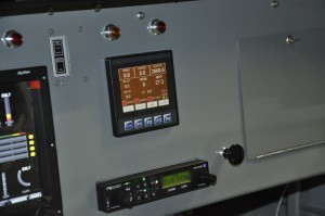
Eagle ECU Interface and Par100EX Radio

Eagle ECU Interface and Par100EX Radio

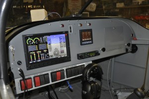
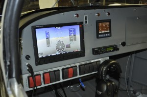
Its been a long time since the last RV9A building update. I have been working away at a steady rate, completing the electrical work in the cabin area. The Eagle ECU interface is working well, communicating with both left and right engine control computers and a Garmin GPS module. I built a backup navigation system into this interface which works really well when you fly east but when you fly west the heading indication gets screwed up. I’ll work at debugging that little issue when more time is available for doing those optional tasks.Inst Panel 3I finally broke down and ordered the 10″ Skyview display in late February. The Loonie was loosing strenght against the USD and the cost of the display was increasing on a daily basis. The cutout in the panel which was made a year ago fit perfectly along with the six mounting holes. The Skyview is a great Primary Flight Display, Engine Monitor and moving map package. I will also order the transponder module next year once the 40 hours of flying in a 25 NM circle are done and I have the need to fly into busier airports.

10" Skyview in split mode

10″ Skyview in split mode

The final cool item is the PS Engineering PAR100EX Radio and Intercom package. The Panel Faceplate has the intercom controls on the left side and radio controls on the right. The actual radio is a Microair 760 transciever which is attached to the bottom on the map box. Cool thing about the Intecom is the Blue Tooth interface which allows me to  connect to my IPhone for music and making/receiving telephone calls. The Lightspeed headset works very well for making the calls, clear on both ends.I still have to get the laser cut labels made for all the switches, knobs and dials. These will be done by Dave at Dave’s Woodcraft in Stettler. He did my 701 labels 15 years ago and they are still looking great.

Finally, the weather co-operates

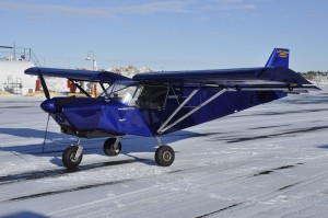
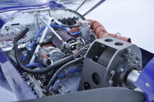
_DSC0004 IMG_0218_DSC0002 _DSC0003I have been waiting for the winter to relax and give us some warm calm weather. Finally temperatures on the plus side on a weekend. I dropped the pitch on the prop by one more degree to 13.5 degrees. This pitch allows the engine to hit 5000 rpm static rpm during the takeoff roll and climb out. 5000 rpm delivers max hp from the engine and best takoff and climb performance. I flew the patch for an hour varying the rpm between 4200 and 4800 as I attempt to break in the engine. Oil temps are a little higher than normal (as compared to my old engine) running around 200 to 220 deg.C. That should improve as the engine breaks in. The aircraft flight characteristics have really changed with the repositioning of the engine angle. The prop was previously not perpendicular to the longitudial axis of the aircraft with the old motor mounts. Their softness has allowed the engine to droop down 3 degrees. New motor mounts have eliminated the droop and now thrust is in line with the aircraft. I cruise an easy 10 mph faster and landings are easier with a lower angle of attack. Less of a drag and drop effect which I was quite used to.

I still have a number of clean up items to do following the engine upgrade. Most are in the cabin to complete wiring of the various warning lamps for alternator, low oil pressure switch and SDS computer trouble. I’ll wrap those up as time permits. I also want to use the 701 as a test bed for my RV9A engine monitor which I have designed and programmed. There are a number of GPS based screens for backup navigation and position reporting that are best tested in a flying aircraft. More on that as this year progresses.