Final Inspection Completed

On Friday the 19th the Final Inspection of TLL was completed by Jerry Mulder representing the MD-RA. Jerry had completed the pre-cover inspection of TLL in 2010. Jerry and his son John had also completed the precover on my CH701 sometime in the mid 90’s (don’t recall exactly when). Fortunately Jerry and I have known each other for many years thru our various affiliations with recreational aviation in central Alberta. The inspection took the better part of 5 hours to complete with the time split about 50/50 between the aircraft and paperwork completion. There were a few minor items to attend to following the inspection, mostly washers and threads showing, too many threads in a couple of cases and not enough in a few more.

Jerry has to send off the completed paperwork for a peer review before I actually receive my temporary certificate of airworthiness. Once I receieve that C of A I can start the flying program.

I have a very experienced test pilot lined up for the first 5 hours of flying. Although I had the RV transition training in July, I am required by law to have at least 100 hours of experience in “type” to fly the first 5 hours. As my test pilot is an instructor as well, we will put the first 5 hours to good use. I have created a series of test flight “cards” that will allow us to put the aircraft thru a series of test manouvers and exercises. These tests will serve to build my confidence in the aircraft and get performance numbers that can be used in the pilot operating handbook (POH) which I must prepare for TLL.

These test flight cards are here:C-FTLL flight test procedures
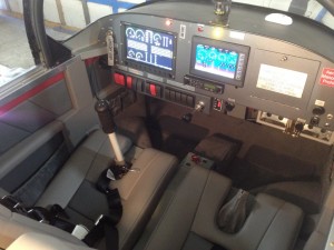
Interior DoneThe interior is installed and I have a few tasks to complete on the cowling before we go flying. We are planning for the first flight in early October. I can hardly wait now that the final inspection is done!

Taxi Testing and ASI

Taxi_testing_ASII taxied Tango Lima Lima up and down the Stettler runway a few times on Sunday at the conclusion of a good snag clean up day. You can see I was heading west on runway 27 when I pressed the screen capture button. Right now I have the F1 key set to capture screen images but I think I will reconfigure it to use one of my joystick pushbuttons. Its been handy to use the screen capture as a means of fixing up the displays and getting all the bars and numbers displaying properly.

The engine idles down smoothly to 760 rpm once its warmed up.

As I was picking up speed, I noticed that my backup ASI came alive with an indicated speed of 9 knots. The Dynon was still sleeping, I’m not sure what speed it starts indicating at but I am sure impressed at the low range of this pressure transmitter. I have another lower range differential pressure transmitter to install on the 701 this winter for backup ASI.ASI1

Final Inspection is scheduled for this coming Friday, working away every evening on misc. tasks to ensure it goes smoothly.

Building your own Glass panel

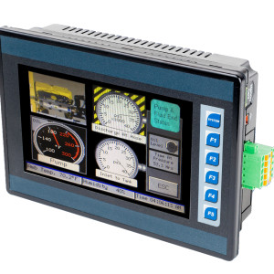
eagle_ecu_hmi_blogWhile its certainly a lot easier to lay out some cash and pick up a ready to fly glass panel, its highly unlikely you will find one that will communicate with your Precision Airmotive Eagle ECU. That was my challenge. Once I discovered that the Eagle ECU supported the industry standard Modbus communications protocol, the main hurdle had been crossed. The next was finding a display that would function in a bright cockpit and aviation environment. An American company called Horner has been designing and manufacturing programable controllers and control screens for years and I had been using them in a multitude of industrial and agricultural applications with success. It wasn’t until they rolled out the XL7 product line that the final hurdles could be overcome. A display that comes close to my Dynon skyview for brightness. It is touch activated and has hard keys along its right side. The unit has a number of features that I am exploiting for my application.XL7_FaceAngle_1_RGB-300x300

Present design interfaces to a GPS puck, the two Eagle ECUs and the Dynon serial data port. I also included a separate airspeed transducer to act as backup to Dynon. Its been a bit of work making it all come together over the last year. This unit will never replace a Dynon or Garmin for synthetic vision or moving maps but it does sweet work with trend displays and the handling of large packages of data. In the event of a Dynon failure, I can still safely fly and navigate my way to a safe landing site.The programming software which can be freely downloaded from the Horner website allows the user to program applications for whatever their creative minds desire. I’ll explain what I have done as time permits in future posts to this blog.

Here is a summary of the XL7 from the company web site:

  • All units feature a high-resolution wide aspect ratio 7″ WVGA Color Touch Screen with 1000 nits of brightness. The innovative display provides high outdoor visibility and allows the XL7 to be used in a wide variety of ambient condition applications.
  • Built-in digital & analog I/O with two 1MHz high-speed counters
  • Dual 10/100 Ethernet for factory and world-wide networking adding flexibility when linking to factory networks like Modbus/TCP and Ethernet/IP, while performing standard functions such as: web serving, FTP file transfer, E-mail and protocol support.
  • Dual CAN Ports for fieldbus flexibility. One port utilizes CsCAN for Distributed Plug and Play I/O over a 500m distance. The second port provides support for CANopen and J1939 for mobile applications
  • USB 2.0 Ports for programming & FLASH drive support
  • 32GB microSD Slot for Virtually Unlimited Data Logging

Its not my desire to market or prosper from what I am presenting here, just share what I have done and help you roll your own if you are so inclined.

Fuel Flow Tests

climb_fuel_flowThe Fuel Flow test demonstrates that the fuel pump is capable of delivering at least 125% of the fuel required by the engine under a high angle climb. This test also proves that all piping, screens and filters are clear and clean. For this test the following criteria were used:

The test climb angle is based upon a rate of climb of 2000 FPM. This is rate of climb is higher than the Van’s factory advertised ROC of 1900 FPM. Using 110 MPH as the climb speed covering a distance of 9680 feet in one minute results in a climb angle of 11.6 degrees.

The aircraft cabin rails were used as the reference for level and climb angle. A digital protractor was used to set the aircraft to 11.7 degrees. Blocking was used under the nose wheel to maintain this angle.

The fuel system was tapped into at an unused 3/8” port on the firewall gascolator. AN6 fittings and 3/8 AL tubing was used to run the fuel sample to a catch container.

The minimum fuel to be drawn from a fuel tank was added to each tank. This minimum fuel is determined by the formula:   1/12*180/2=7.5 lbs. At 6 lbs per USG the minimum fuel is determined to be 1.25 USG or (1.04 Imp.Gal.) or 4.73 litres.

Five litres of fuel was added to each tank. The right fuel tank was selected and the boost pump was run for 1 minute. The fuel collected after 1 minute was measured in a graduated cylinder as 3.81 litres. The test was repeated for the left fuel tank. The fuel collected was measure as 3.75 litres.

A fuel flow of 3.8 l/min equals 228 litres/hr. This converts to approximately 60.23 USG/hr. Using the formula of: .55lbs of fuel *180hp/6lbs per gal= 16.5 USG/hr as maximum fuel requirement.

Conclusion: The electric boost pump and fuel delivery tubing is more than capable of supplying the fuel requirements of the aircraft in a high angle of climb. Required = 16.5 USG/hr , Capable = 60.2 USG/hr.

Fixing the weeper

leak_fix2I hooked the fuel tank up to a vacuum pump and fitted a low range guage to one of the tank fittings. I pulled a 1″ WC vacuum on the tank and sprayed the Loctit 7649 primer on the leak seam. I waited for a few minutes for the primer to work its way into the leak and then dabbed a few drops of Loctite Green 290 on the leak area. I left the vacuum on for a couple of minutes and them shut the pump off. I let the vacuum bleed off and then left the tank to cure for 4 hours. I repeated the pressure test with snoop and the bubbles did not appear. I re-installed the tank the following day. The installation only took an hour to complete. I picked up a very compact 1/4″ ratchet drive that helped speed up the job.

Fuel was added to the tank and after 24 hours there was no sign of any fuel leak. Success! Now on to fuel flow and weight and balance tasks.